DateTime:2016/12/14 0:00:00
l Supports Links up to 30m using Cat 6a/7 Cable
l SFF-8431 and SFF-8432 MSA Compliant
l IEEE 802.3az Compliant
l Low Power Consumption (2.5W MAX @ 30m)
l Fast Retrain EMI Cancellation Algorithm
l Low EMI Emissions
l I2C 2 Wire Serial Interface for Serial Id and Phy Registers
l Auto-negotiates with other 10GBase-T PHYs
l Supports 100/1000Base-T
l MDI/MDIX Crossover
l Multiple Loopback Modes for Testing and Troubleshooting
l Built-in Cable Monitoring and Link Diagnostic Features
² Cable length measurements
² Opens/shorts
l Robust Die Cast Housing
l Bail Latch Style ejector mechanism
l Unshielded and Shielded cable support
Overview
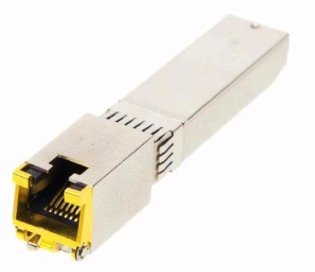
The SOSP-10G-RJ45 module is a high performance integrated duplex data link for bi-
directional communication over copper cable. It is specifically designed for high speed
communication links that require 10 Gigabit Ethernet over Cat 6a/7 cable. This is the first SFP+
transceiver that offers 10 Gb/s communication over this type of media.
Regulatory Requirements
The SFP transceiver installed into the host system requires meeting Compliance Requirements listed in this paragraph.
In order to achieve this, the module must be evaluated in considering its use in the equipment designs. Unless otherwise specified, the transceiver module shall meet the current version, at the time of manufacturing, of the applicable EMI/EMC specifications for telecommunication network and information technology/multimedia equipment.
Radiated Emission (RE)
The 10G Base-T CuSFP transceiver shall meet the applicable FCC Part 15 emission requirements.
10G Base-T CuSFP transceiver minimum emission requirements are:
l Class B radiated emission requirements by using shielded cables at least 4dB margin.
10.0 KHz – 18.0 GHz is recommended frequency range for radiated emission testing.
Electrostatic Discharge (ESD)
In addition the the CuSFP module or host platform shall not show susceptibility to conducted immunity when applied to the interface cable per the requirements of IEC 6100-4-2:
- Contact ESD only to the accessible portions of the module (i.e. front panel connector receptacle). 8 kV - Air Discharge and 4 kV – Contact discharge.
l Criteria B (see paragraph 6.7 for Criteria’s definition) should be used as a measurable effect from ESD applied (25 discharges by polarity – both air/contact) to the system used with CuSFP modules
Traffic generation and Susceptibility criteria.
Traffic generation and monitoring.
A minimum 50% utilization will should be established for preliminary investigation when possible, with final evaluation being performed with a worst-case utilization.
Susceptibility Criteria:
The disturbances will be applied to the system as a whole. Data losses will be reported according to the following:
Performance Criteria:
Performance Criteria A
During the test and after the test, system with CuSFP module shall continue to operate:
- without degradation resulting in no greater than 1% of packets per second dropped,
- with zero requests for retry, beyond requests resulting from the 1% per second allowable data loss
- with no degradation in the data transmission rate, beyond requests resulting from the 1% per second allowable data loss
- without protocol failure
- without loss of link
- without alarm signaling triggered.
Monitoring Method:
The Traffic Generator will be monitored. The link, speed, retry rates, etc, status during the test will be reviewed by equipment status logs after the test, and monitored by LED observation during the test.
Performance Criteria B
Error rate, request for retry and speed of data transmission rate may be degraded during the application of the test. Degradation of the performance as described in criteria A is permitted provided that the normal operation of the EUT is selfrecoverable to the condition immediately before the application of the test. In these cases, operator response is not permitted to re-initiate an operation.
Monitoring Method:
The Traffic Generator will be monitored. The link, speed, retry rates, etc, status during the test will be reviewed by equipment status logs after the test, and monitored by LED observation during the test.
Performance Criteria C
Degradation of the performance as described in criteria A is permitted provided that the normal operation of the EUT is selfrecoverable to the condition immediately before the application of the test or can be restored after the test by the operator.
Monitoring Method:
The Traffic Generator will be monitored. The link, speed, retry rates, etc, status during the test will be reviewed by equipment status logs after the test, and monitored by LED observation during the test. .
Flammability
The PCB of the SFP module shall be min. V-0 UL flame rated. Applicable standards: UL/CSA 60950 and IEC 60950.
Environmental and Quality Requirements
Accelerated Aging
The SFP+ transceiver module shall be subjected to an accelerated aging test that exposes the module to 85C case temperature while being powered at 3.3V for 2000 hours.
Failure criteria: The product is considered to have failed this test if any of the following occurred: 1. Failure of test unit to perform ping or traffic test;
2. Excessive corrosion of components.
Relative Humidity (Non-Operational)
The SFP+ transceiver module shall be subjected to the temperature and humidity profile as per MIL STD 202G Method 103B,
- Test description: The module shall be subjected to the temperature and humidity profile of 85C/85% RH for 1000 hours. The product shall be non-operational during this entire period.
- Failure criteria: The product is considered to have failed this test if any of the following occurred:
1. Failure of test unit to perform ping or traffic test;
2. Excessive corrosion of components.
Shock and Vibration
l 16 10G Base-T SFP+ copper transceivers shall be subject to mechanical shock test and vibration test.
l Mechanical shock test
The mechanical shock test shall use the following specification: A half-sine wave shock shall be applied on the DUT, 5 times per direction for 6 directions. Peak acceleration of the input 1500G. Pulse width of half-sine wave 0.5ms.
l Vibration test
The vibration test shall use the following specification: A random vibration input for a period of 4 min per cycle, 4 cycle per axis. The input acceleration level shall be 20G over the frequency band of 20 to 2000 Hz.
l Failure criteria: The product is considered to have failed this test if any of the following occurred:
1. Failure of test unit to perform ping or traffic test;
2. Excessive corrosion of components.
v